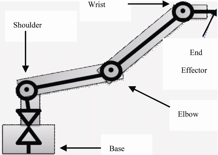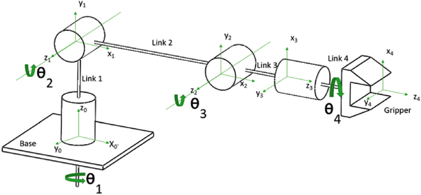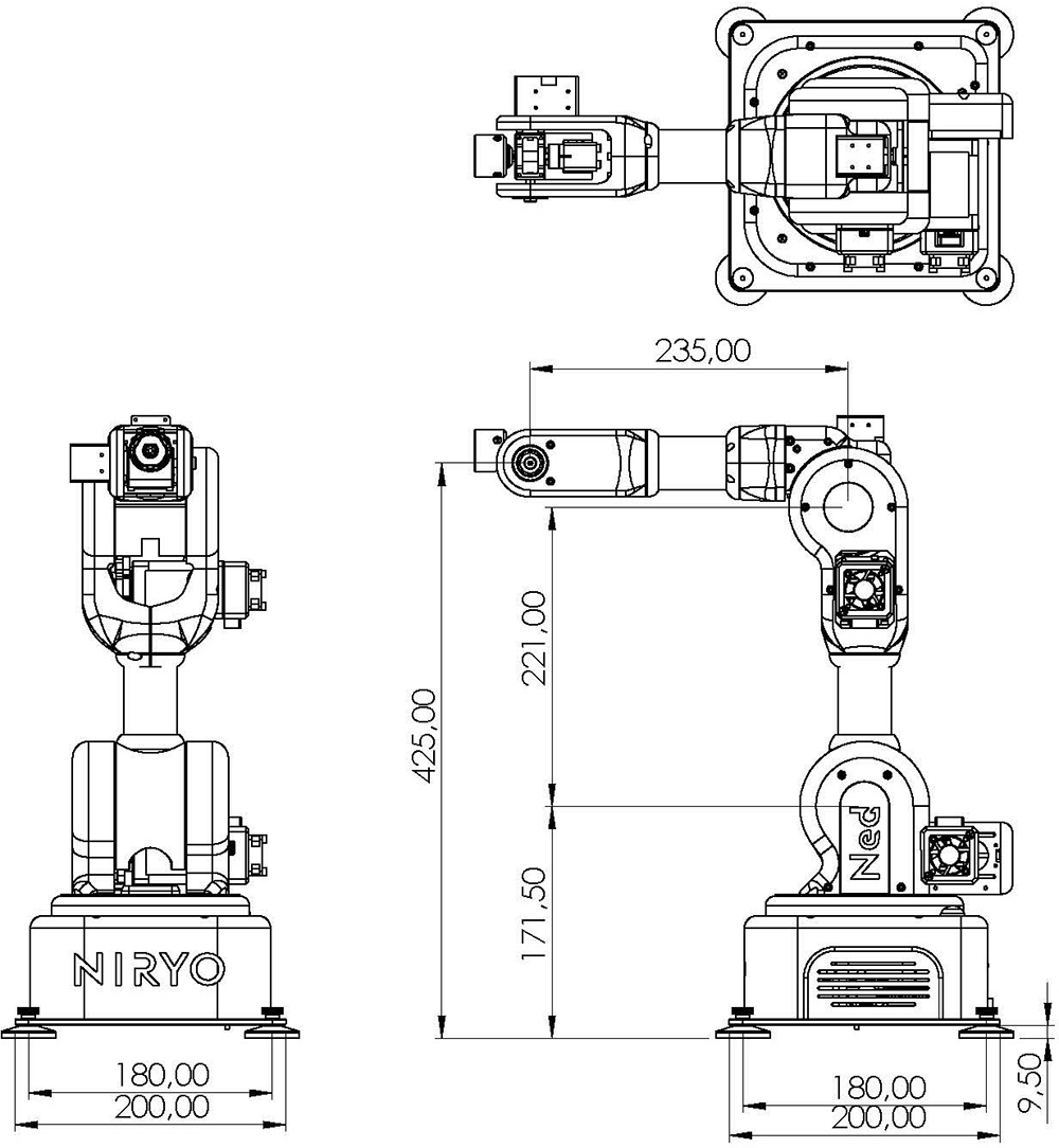
Design Process
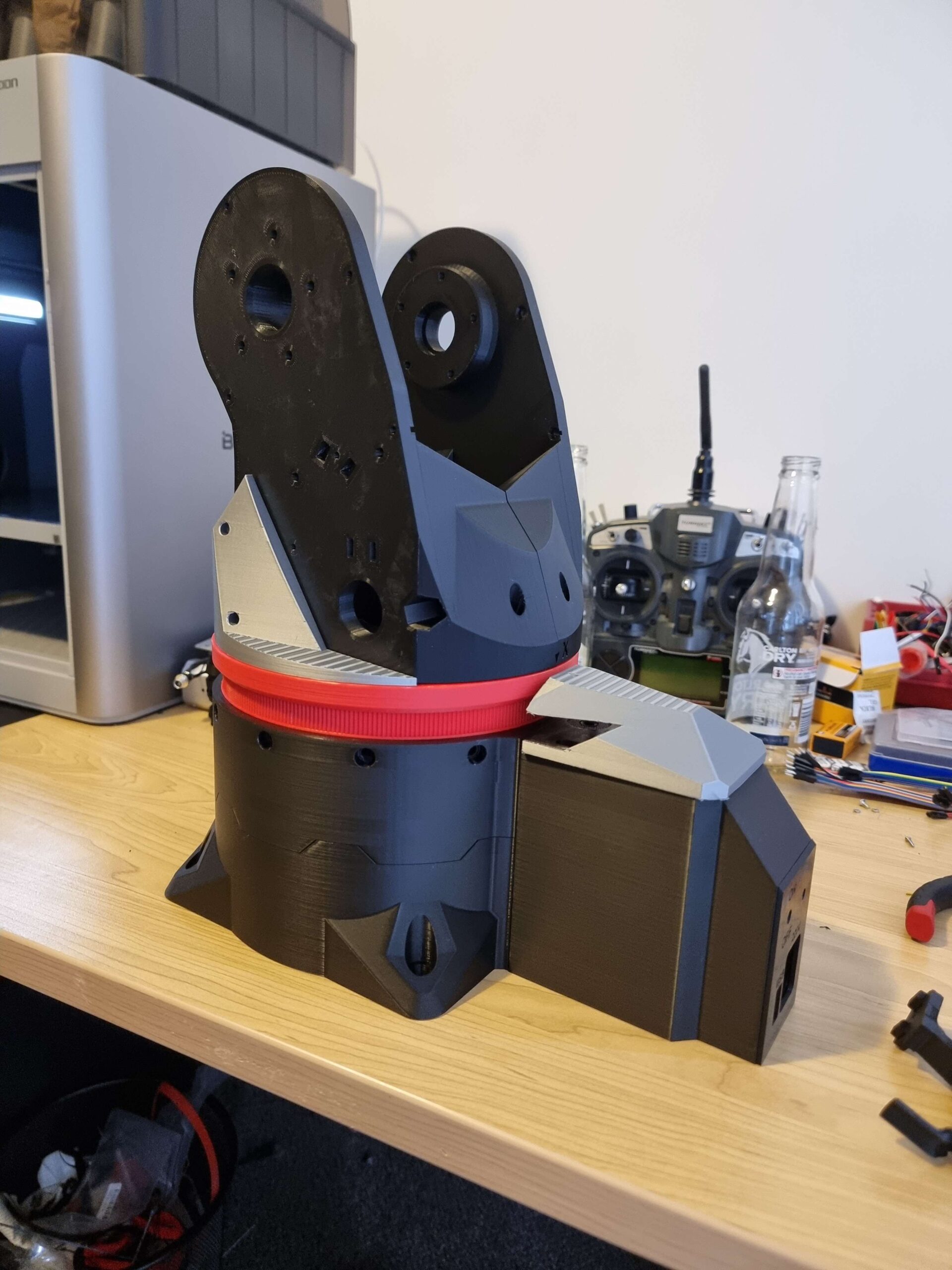
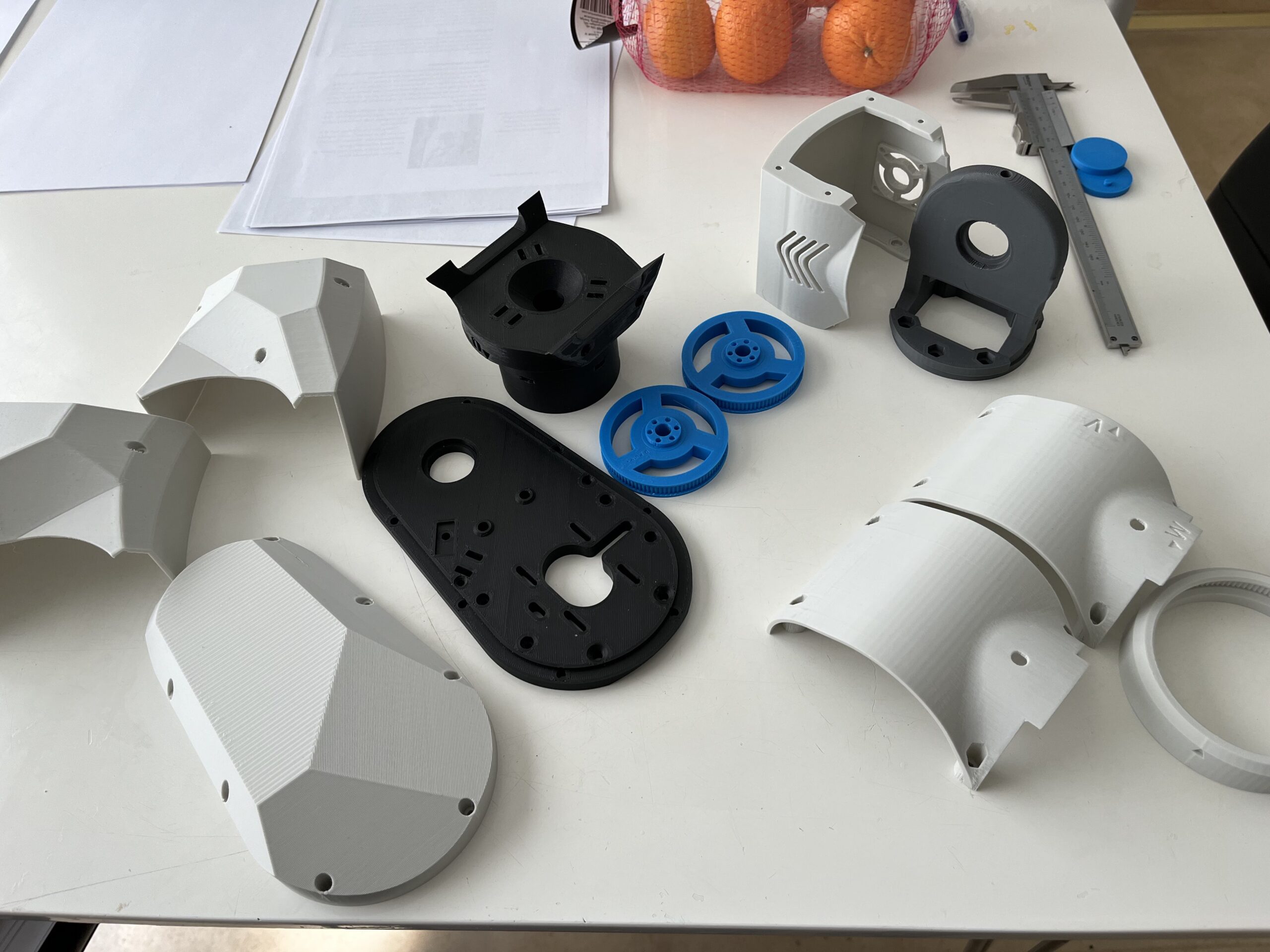
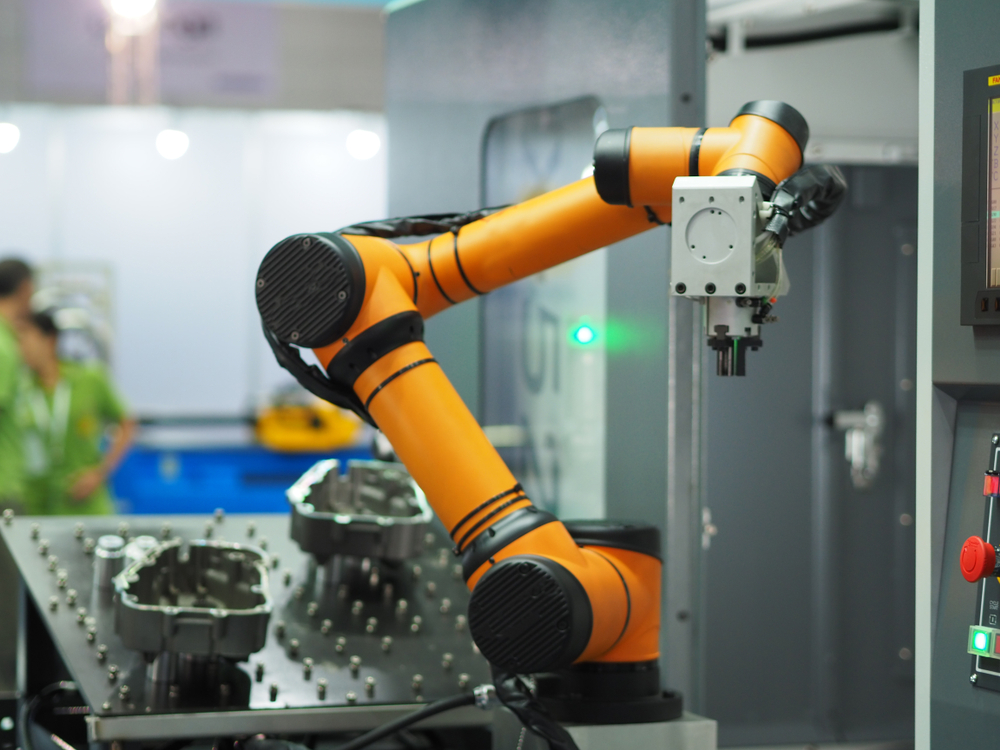
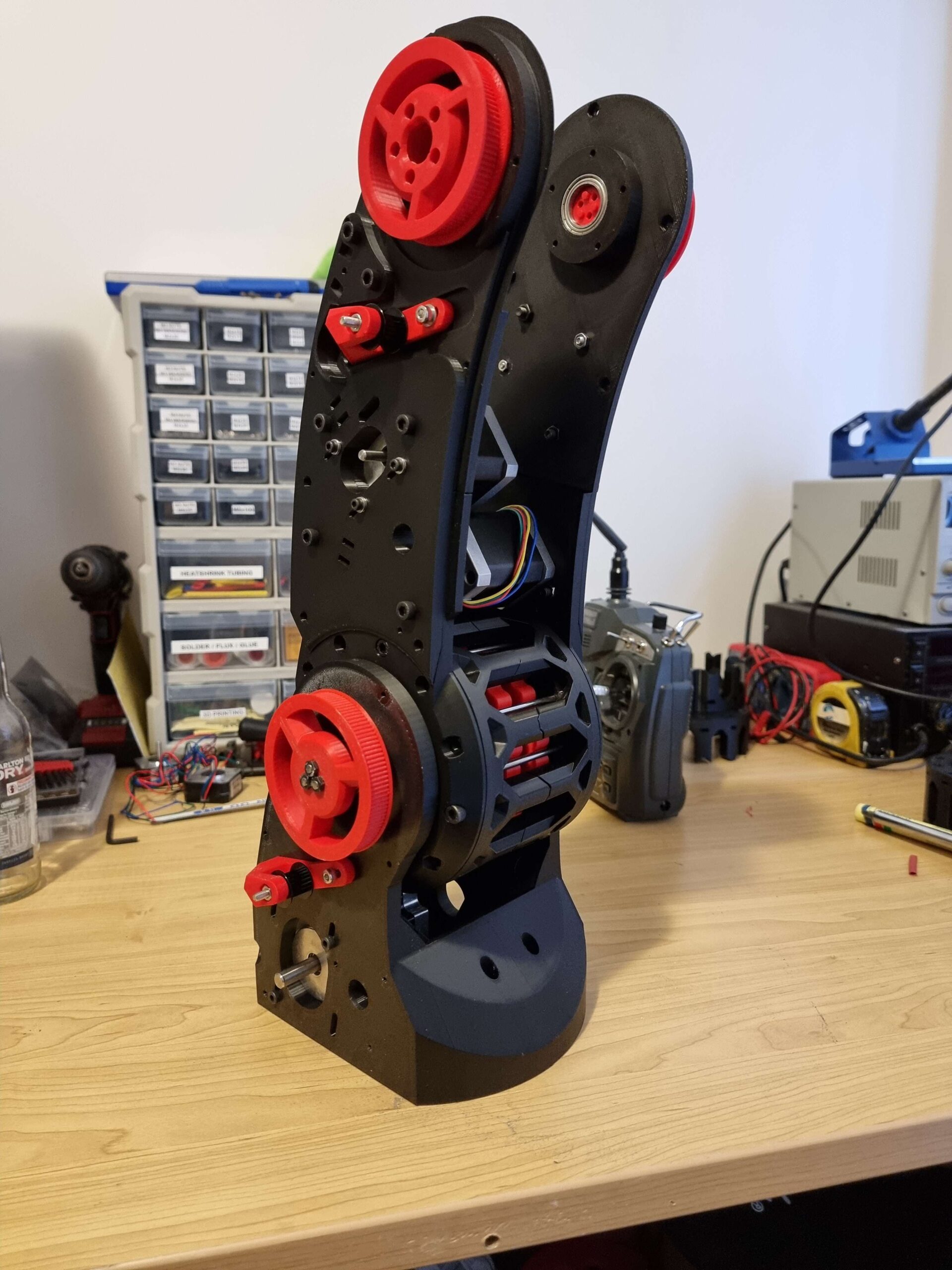
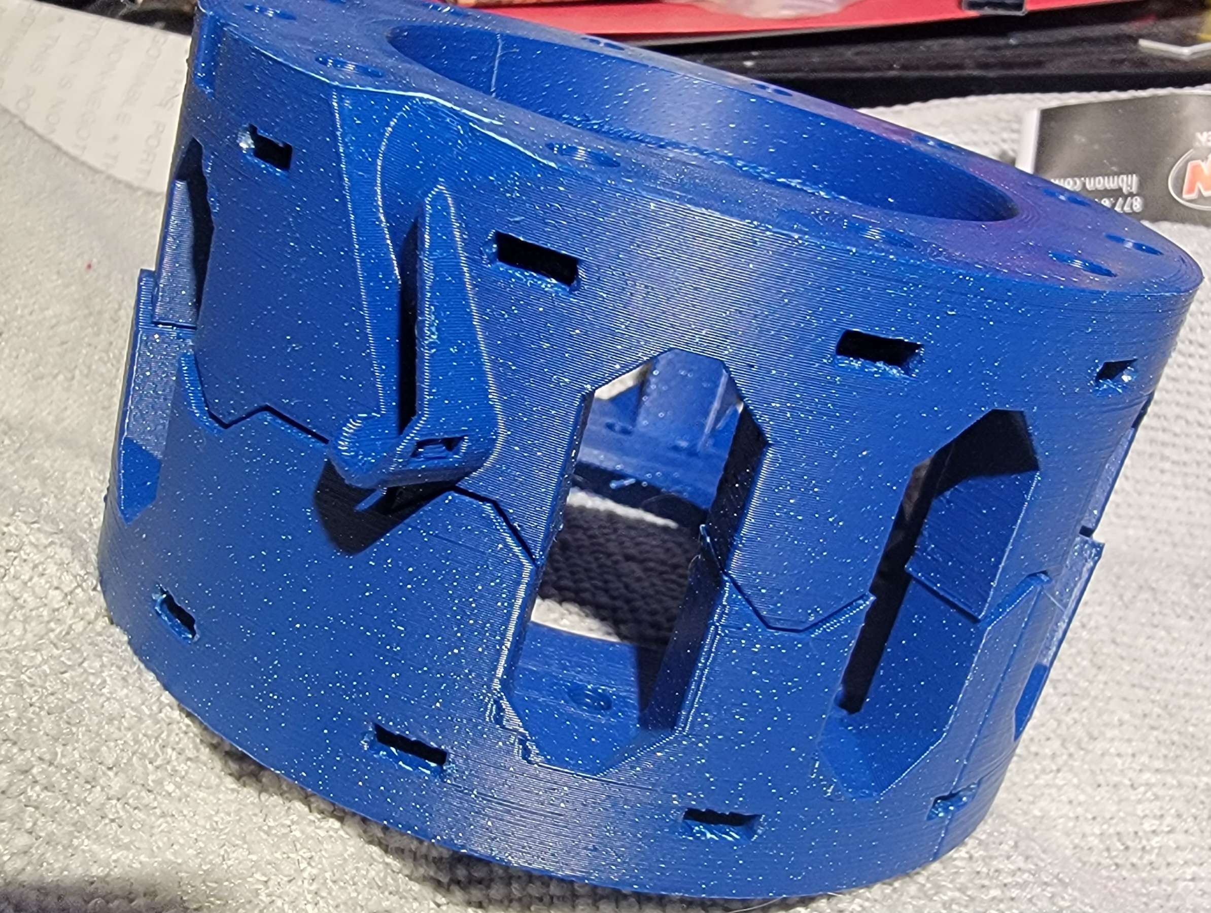
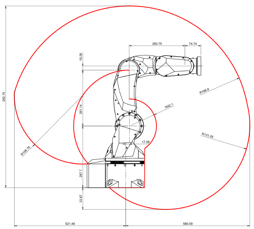
The design process for our 6-axis robotic arm project was extensive and detailed, involving numerous stages of CAD design, trial and error, and hands-on adjustments. We created a total of 175 individual CAD designs, many of which required multiple iterations and corrections due to failed prints. The image above shows the unofficial design during the assembly phase, highlighting the dimensions and structure of the robotic arm. Key dimensions include a reach radius of 1056.78 mm, a height of 282.75 mm, and various arm segment lengths that contribute to the overall flexibility and range of motion.
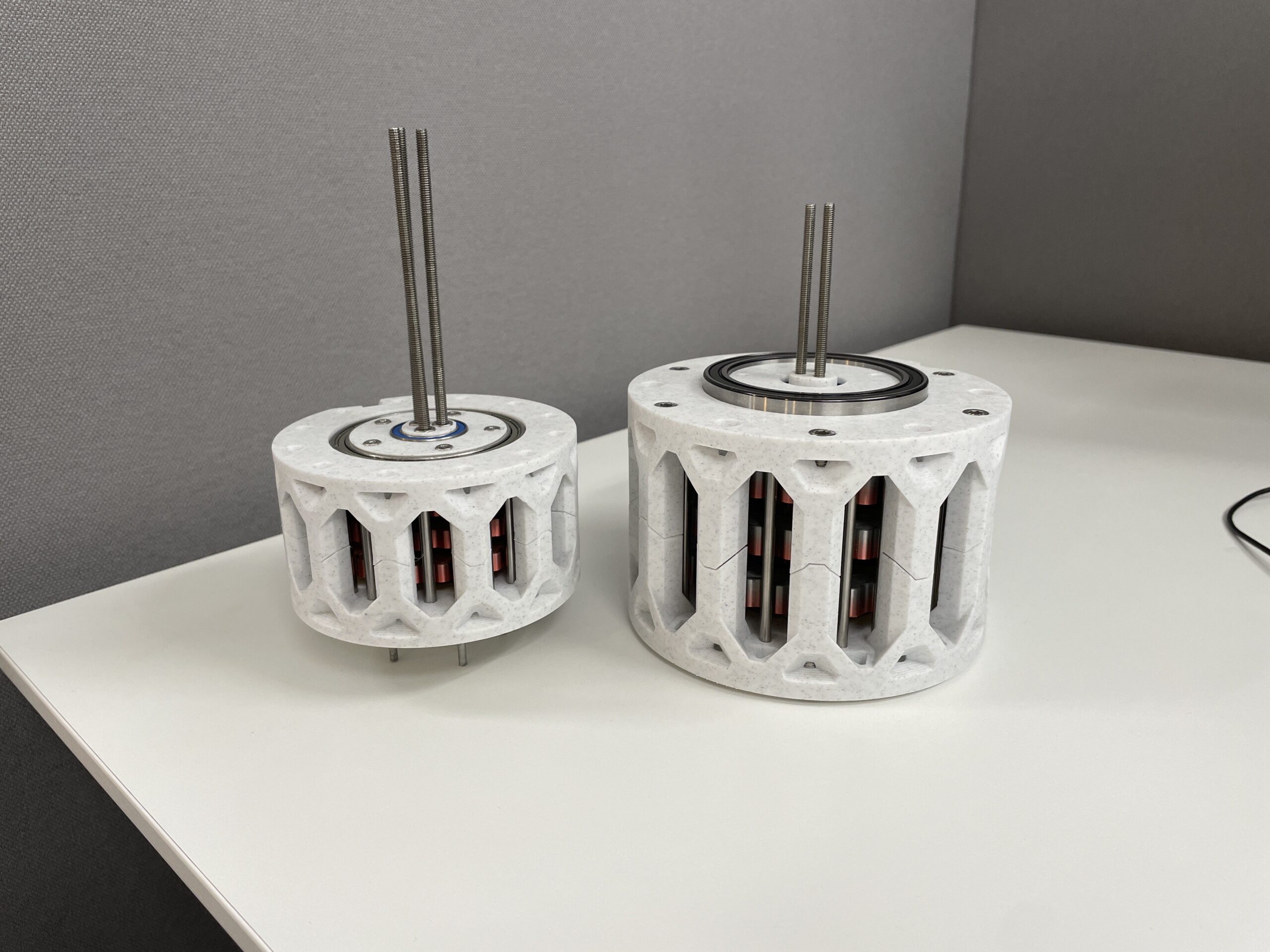
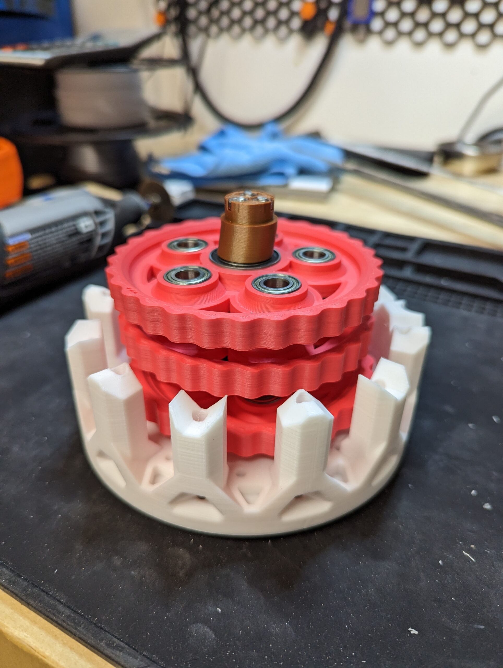
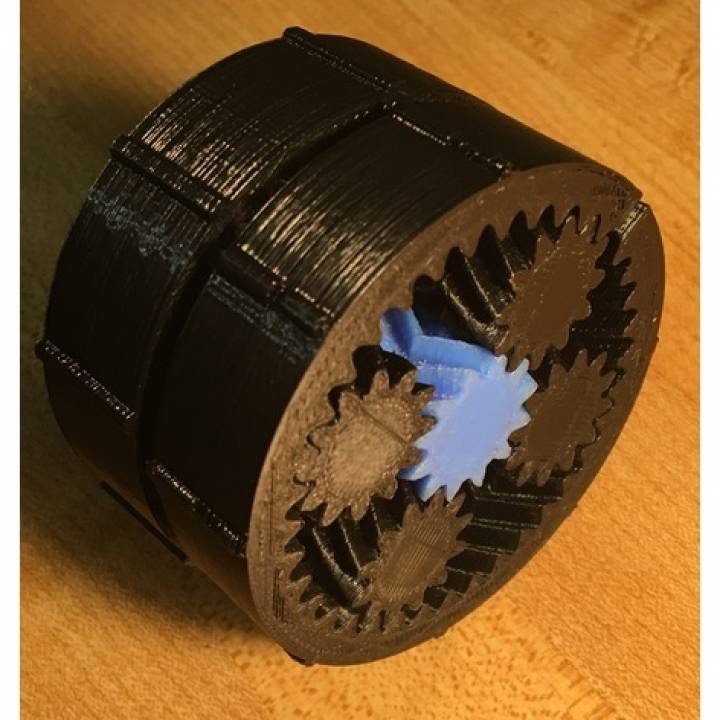
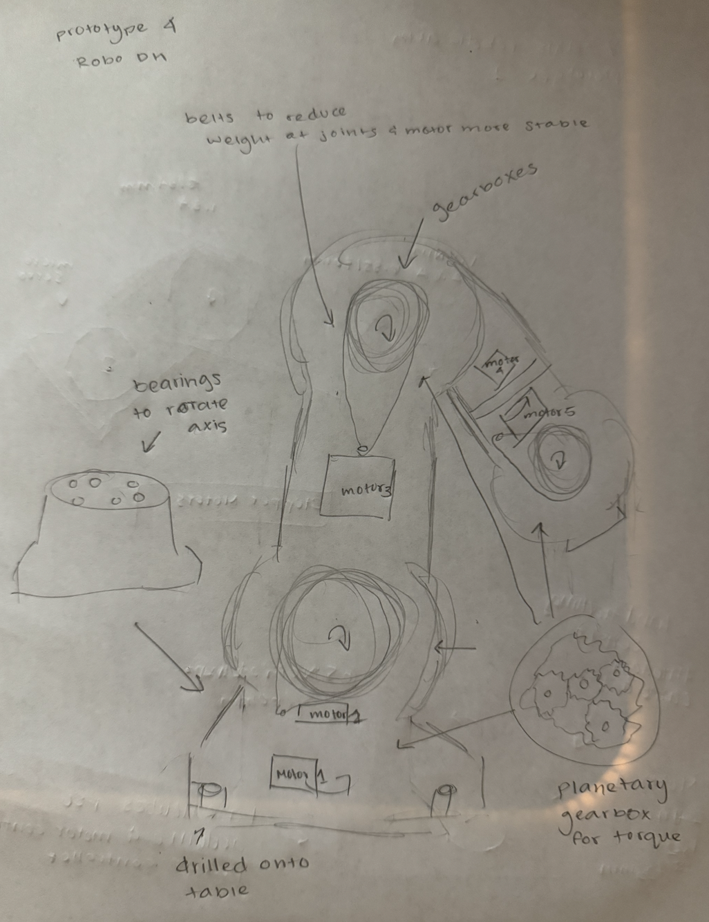
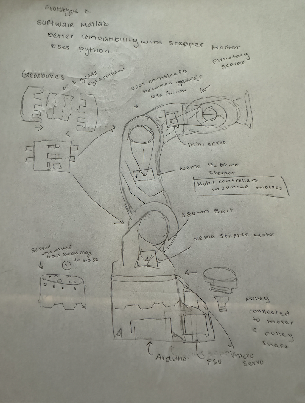
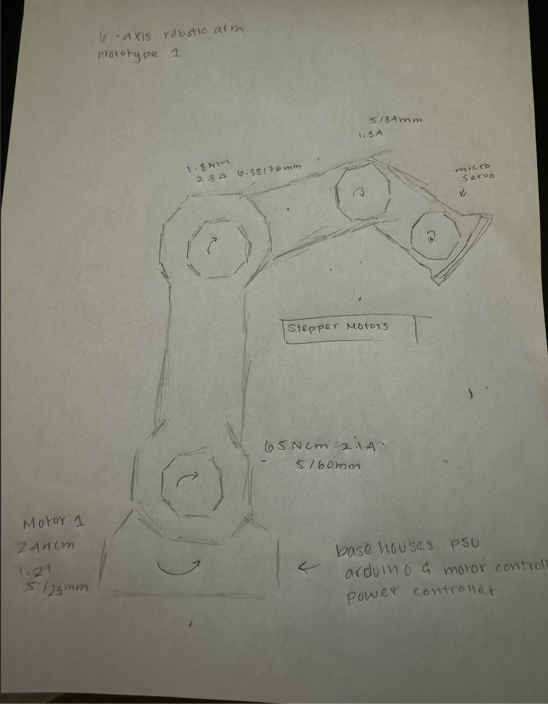
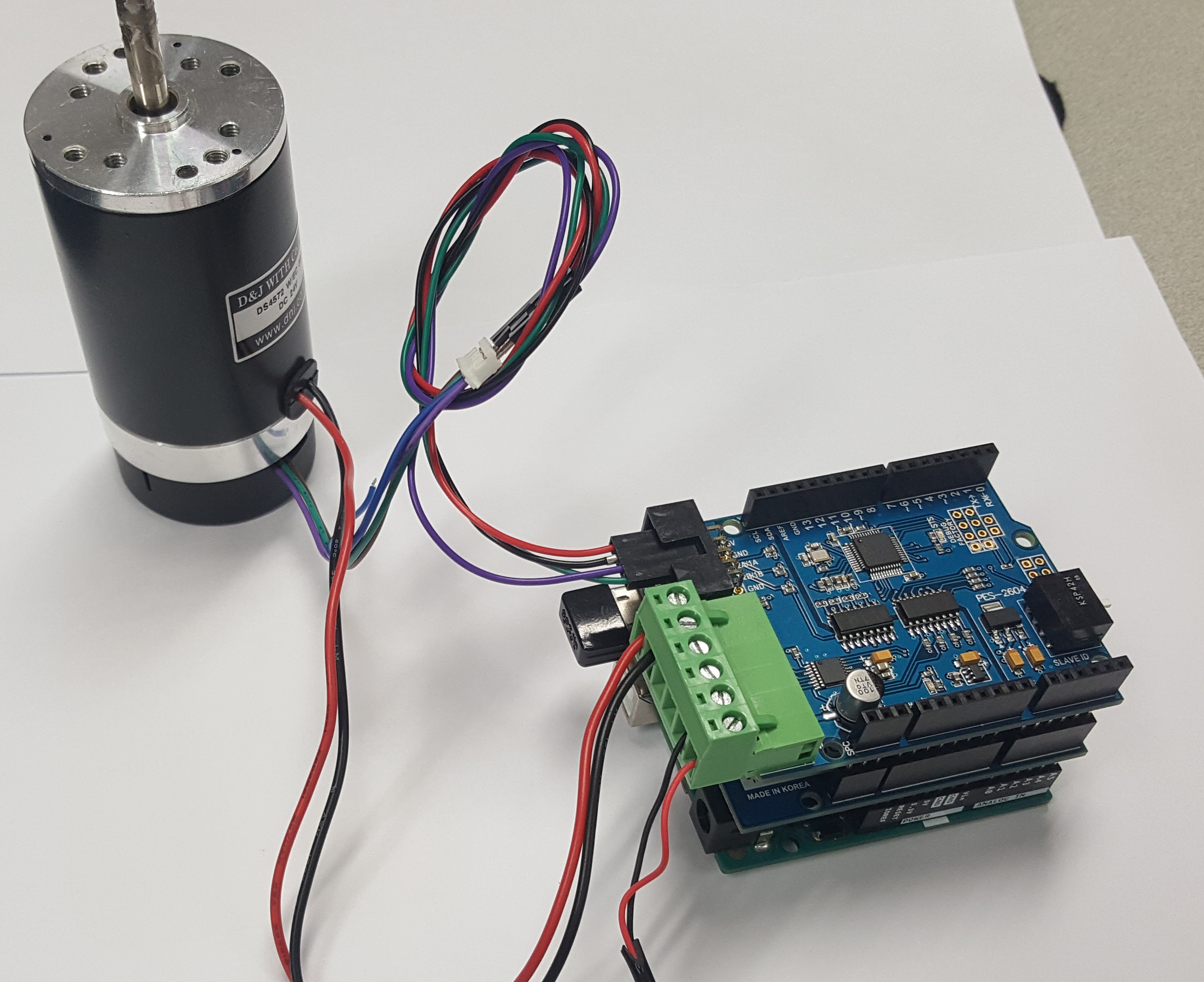
Our approach combined digital and traditional methods. We began with paper sketches to conceptualize our ideas before translating them into CAD models using Onshape. This process involved significant trial and error, with frequent adjustments to improve precision and functionality. Throughout the design and assembly phases, we sanded and spray-painted components to ensure a smooth finish and professional appearance. Our project aimed to build a 6-axis industrial robotic arm using components such as DC motors, gearboxes, motor controllers, chain drives, and bearings. The process was pre-meditated, with a clear vision and detailed planning to guide us from initial sketches to the final assembly.